By AIDU | 25 May 2023 | 0 Comments
MLB-360 CAMERA INSTALL
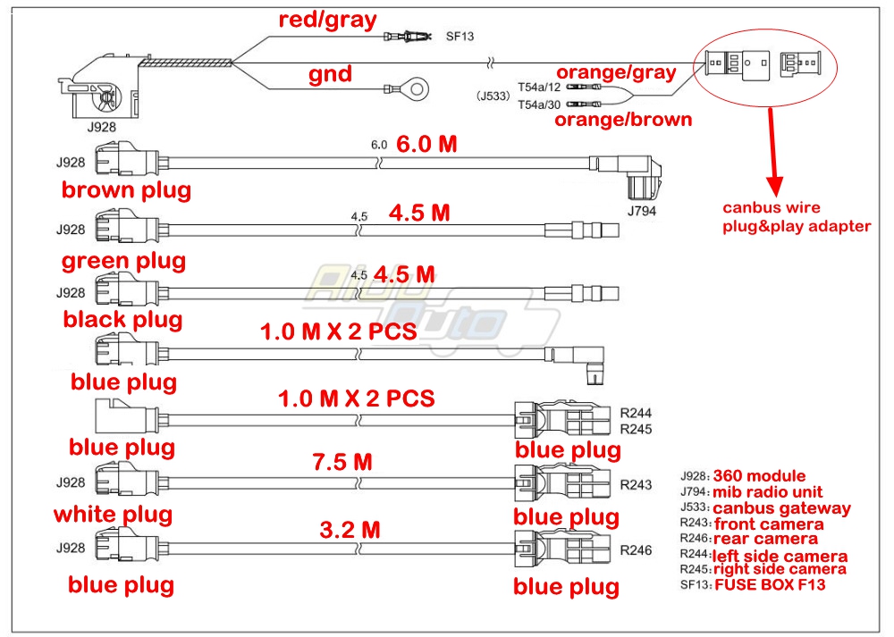
circuit diagram :
------------------------------------------------------------------------------------------------------------------------------------------------------------------------------------------------------------------------------------------
Codeing :
1. 6C- 360 Module - data transfer (send email address . will send you parameter)
2. 6C long code : Q5 FY : 02240601BE0FA10008404004 A4/A5 B9 : 02940201BE0FA10008004084
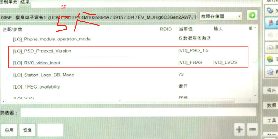
3. 5F Adaptation : (Find _RVC_video_input and _FBAS and change it to _LVDS)
4. 09 ---- camera_variant----vps_installed
5. 6C - Calibration CAMERA (Need use VAS721001 )
you can buy VAS721001 from :
https://www.aliexpress.com/item/32913651135.html
t The two exterior mirrors must have been folded out.
t The parking brake is tightened.
t The steering wheel is in the zero position and the wheels are straight forward.
t All doors and luggage compartment lids are closed.
t There are no people in the car.
t The vehicle is not loaded (empty weight).
t The battery charger is connected, and the battery charger must not be within the sight of the camera.
t The ignition switch is turned on.
t The system is activated and displayed on the display unit -J685- of the front information display and operation unit controller.
t Do not move the car during calibration.
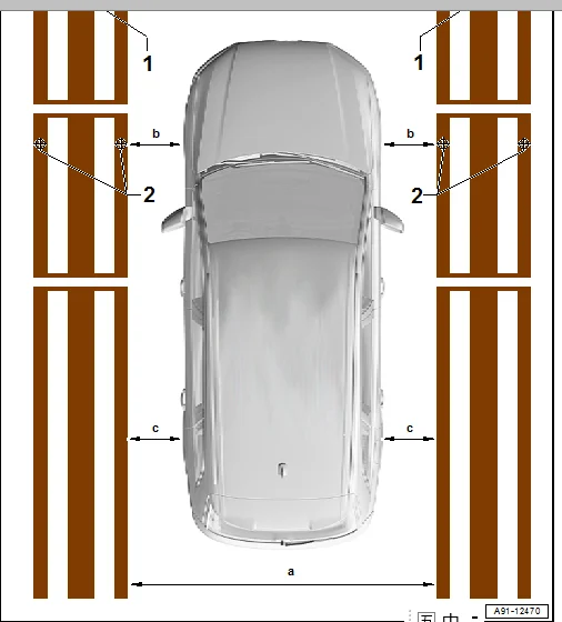
Prerequisites for calibration table/calibration environment
l Flat calibration surface
l There must be no objects in the surrounding environment of the calibration area to avoid line recognition errors.
l Uniform light (no headlights or direct lighting) to avoid strong light differences
l Dimensions -a- 2000 to 2500 mm ± 5 mm, the front and rear are the same
l Dimensions -b- must be the same on both sides
l Dimensions -c- must be the same on both sides


------------------------------------------------------------------------------------------------------------------------------------------------------------------------------------------------------------------------------------------
Codeing :
1. 6C- 360 Module - data transfer (send email address . will send you parameter)
2. 6C long code : Q5 FY : 02240601BE0FA10008404004 A4/A5 B9 : 02940201BE0FA10008004084
3. 5F Adaptation : (Find _RVC_video_input and _FBAS and change it to _LVDS)
4. 09 ---- camera_variant----vps_installed

5. 6C - Calibration CAMERA (Need use VAS721001 )
you can buy VAS721001 from :
https://www.aliexpress.com/item/32913651135.html
The camera lens must be clean, the camera lens can only be cleaned with wet wipes.
t Detect the camera image on the display unit -J685- of the front information display and operation unit controller. If the image is affected by damage to a camera, replace the corresponding camera. If the image is tilted, check the fixation of the corresponding camera.t The two exterior mirrors must have been folded out.
t The parking brake is tightened.
t The steering wheel is in the zero position and the wheels are straight forward.
t All doors and luggage compartment lids are closed.
t There are no people in the car.
t The vehicle is not loaded (empty weight).
t The battery charger is connected, and the battery charger must not be within the sight of the camera.
t The ignition switch is turned on.
t The system is activated and displayed on the display unit -J685- of the front information display and operation unit controller.
t Do not move the car during calibration.
Prerequisites for calibration table/calibration environment
l Flat calibration surface
l There must be no objects in the surrounding environment of the calibration area to avoid line recognition errors.
l Uniform light (no headlights or direct lighting) to avoid strong light differences
– Position the two calibration templates in parallel. The car must be centered between the two calibration templates.
Note the following:l Dimensions -a- 2000 to 2500 mm ± 5 mm, the front and rear are the same
l Dimensions -b- must be the same on both sides
l Dimensions -c- must be the same on both sides
Leave a Reply
Your email address will not be published.Required fields are marked. *